A tank pump needs a clear command: start filling, stop draining, raise an alarm, or shut down before the liquid reaches a dangerous level. By the end, you will understand how float movement becomes an electrical signal, how to wire that signal into a safe control circuit, and how to choose a switch that will keep working in the actual tank environment.
Key takeaways
- Use NO or NC contacts to match the pump, valve or alarm logic.
- Add separate high- and low-level points to limit cycling and detect faults.
- Match float materials and construction to tank geometry and liquid chemistry.
- Confirm voltage, current, inrush rating and protection before switching a load.
How a Float Turns Liquid Movement into an Electrical Signal
A float switch detects tank level when buoyancy moves a float as liquid rises or falls. That movement shifts a stem, magnet, or mechanical arm until it actuates an internal contact at a fixed elevation.
This float switch working principle provides point-level detection, not a continuous measurement. The electrical output tells a pump controller, valve, alarm, relay, or PLC that the liquid has crossed a particular threshold; it does not report whether the tank is 37% or 63% full. Continuous level information requires a separate level transmitter.
A single SPDT contact can provide either normally open or normally closed operation. Wiring determines whether the circuit responds when the float rises or falls, but the label alone is not enough: manufacturers may define contact state with the float up, down, or unactuated. Specify the required state at low, normal, and high level.
The float’s movement depends on buoyancy, so liquid density and temperature matter. A float designed for water may lack reserve buoyancy in a low-density liquid, while deposits can add weight or prevent free movement. Either fault can produce a false level signal.
One float gives one switching point. A vertical assembly or several switches can provide separate pump-start, pump-stop, high-level alarm, and dry-run signals, creating distinct information for each control decision.
How NO and NC Contacts Control Pumps, Valves and Alarms
Choose the contact logic from the required action, not from the label alone. A manufacturer may define “normally” with the float down, up, or unactuated, so specify the contact state at low, normal and high level in the installed reference position.
| Contact type | Circuit action | Typical use |
|---|---|---|
| Normally open float switch | Closes at the defined level and energises a relay or input | Start a fill pump, open a solenoid valve control circuit, or trigger a high-level alarm |
| Normally closed float switch | Opens at the defined level and drops out a relay or input | Stop a drain pump, close a filling valve, or signal a low-level or high-level fault |
For pump control wiring, route the float through a control relay or motor contactor rather than directly through the pump’s power conductors unless the switch carries the motor’s starting and locked-rotor load. Add the specified overload relay, short-circuit protection and motor thermal protection; a float contact does not replace them.
A pump-down circuit normally uses a high-level contact to start the pump and a lower-level contact to stop it. One float used for both actions causes rapid start-stop cycling unless the circuit provides latching, a timer or separate switching elevations.
An NC loop can make a broken wire appear as a fault when a monitored relay requires continuous energisation. That is a design choice, not automatic fail-safe protection: changing NO to NC changes the logic, but not the consequences of every cable or relay failure.
How Multiple Level Points Prevent Cycling and Add Protection
Set the pump-start point above the pump-stop point. That vertical gap creates pump hysteresis: the liquid must fall through a defined range before the pump can start again, so waves or minor inflow changes do not switch the motor repeatedly.
Use the level points as a coordinated sequence:
- Pump start: starts the pump when the tank reaches the upper operating level.
- Pump stop: stops it at a lower level after enough liquid has been removed.
- High-level alarm: sits above the start point and warns that inflow exceeds pumping capacity or the pump has failed.
- Low-level cutoff: prevents continued pumping once the tank reaches its minimum operating level.
- Dry-run protection: blocks or stops the pump if the source level falls too far, using a separate low-low float, probe, flow switch or controller input.
A relay or PLC can latch the start command until the stop float changes state. Do not rely on one float to issue both commands unless the circuit adds a timer, latch or built-in differential; one switching point invites rapid cycling.
For duty/standby pumps, the controller must add lead-lag alternation, fault changeover and simultaneous-run logic where required. Wiring two floats in parallel does not alternate pumps. Keep dry-run protection separate from overload, short-circuit and motor thermal protection; a float contact alone cannot perform those functions.
Verify every switching elevation during commissioning because tether swing, tank turbulence and mounting position alter the actual levels.
How to Choose the Mechanical Design for the Tank and Liquid
Choose the design by the float’s movement path, the tank mounting method and the liquid’s behaviour—not by tank capacity alone. A cramped vessel, internal baffles, an inlet jet or an agitator can stop a suitable switch from reaching its setpoint.
| Design | Tank mounting method | Best fit | Main failure risk |
|---|---|---|---|
| Vertical float switch | Top-mounted stem through the tank cover | Clean liquids and narrow vessels needing compact, repeatable switching | Sludge or solids can jam the guide; the magnet, guide and switch geometry determine the differential |
| Horizontal float switch | Side-wall mounting through a sealed boss | Tanks with limited top access or a fixed side-level alarm | Foam, grease or deposits can hold the float up or prevent its arm from moving |
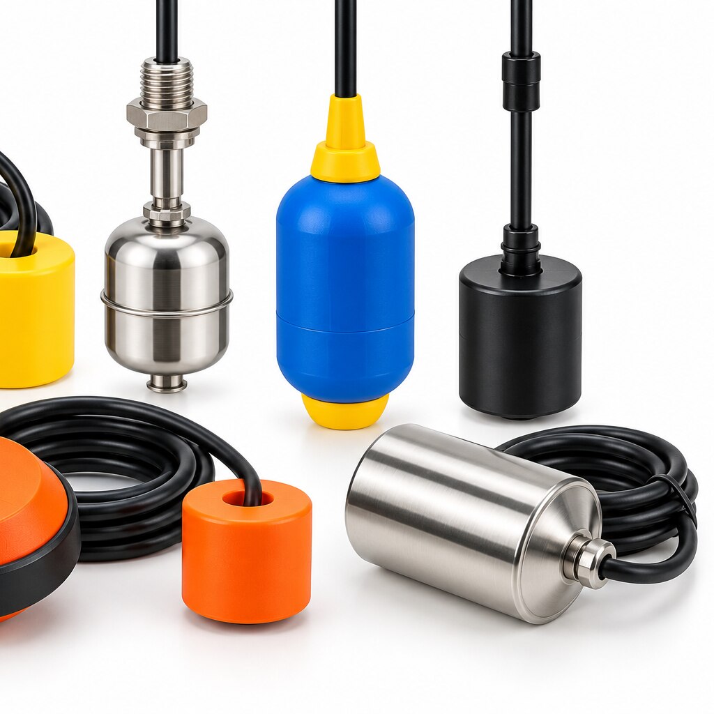
| Tethered float switch | Cable-suspended from the cover or a bracket | Large tanks, sewage and applications needing a wide switching differential | Turbulence, cable entanglement and excessive swing can cause false switching |
Match the wetted float, stem, seal and cable materials to the liquid’s corrosion, temperature, density and viscosity. Foam, floating solids, grease and sludge demand a float shape and guide arrangement that resist fouling; a smooth liquid alone does not prove compatibility.
Keep the switch away from pump discharge, inlet flow and agitators. Use a stilling well, guide tube or mechanical damping when needed, then confirm the required hysteresis: tether length and swing control it in suspended designs, while magnet and guide geometry control it in vertical designs.
In a hazardous location, verify approval for the complete circuit, barrier or isolator, enclosure and installation method—not low voltage alone.
Which Electrical Ratings and Protection Devices Must You Confirm
Confirm the float’s switching voltage, switching current, VA limit and inductive load rating before connecting it to a pump circuit. A printed current value may describe a resistive load, not a motor; inrush current and locked-rotor current can weld small reed contacts even when running current appears acceptable.
| Load arrangement | What it means | When it applies |
|---|---|---|
| Direct pump switching | The float carries motor current and interrupting arcing | Only when the manufacturer rates the contact for the motor’s voltage, inrush current and inductive load |
| Contactor interface | The float energises a relay or motor contactor coil | Preferred when pump current exceeds the float rating |
| PLC or relay input | The float switches a low-energy signal | Use an interface relay when input voltage, current or polarity does not match |
Verify these protection and control components before energising the panel:
- A motor contactor, overload relay and short-circuit protection sized for the pump; the float does not replace any of them.
- Thermal protection or the motor’s specified protective device, plus separate dry-run protection where loss of liquid could damage the pump.
- A flyback diode, TVS suppressor or interposing relay for a DC inductive coil; confirm the suppression method matches the circuit.
- A control delay or hysteresis arrangement if turbulence causes repeated switching. A stilling well or relocated float fixes the disturbance; a timer alone can hide it.
- For hazardous locations, an approved intrinsically safe circuit with the correct barrier or isolator, entity parameters, cable and enclosure.
Dollex Control Panel Accessories can help you compare a float’s contact data with the relay, contactor and protection devices in your panel rather than treating a catalogue current as a motor rating.
Related product
 | Dollex Float Switches provide reliable liquid level detection for tanks, reservoirs, and industrial processes. View product → |
Frequently asked questions
How does a float switch turn liquid movement into an electrical signal?
Buoyancy moves a float as the liquid level changes. A stem, magnet or mechanical arm then actuates an internal contact at a fixed elevation.
When should you use normally open or normally closed contacts?
Use the contact state that produces the required pump, valve or alarm action at the target level. Check the switch diagram and test the circuit before commissioning.
Why use multiple float switches in one tank?
Separate level points can start and stop a pump at different elevations, reduce rapid cycling and provide independent high- or low-level protection.
What should you check before selecting a float switch?
Check tank geometry, mounting space, liquid compatibility, float movement, contact arrangement, voltage, current, inrush load and the required protection device.