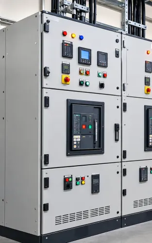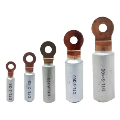
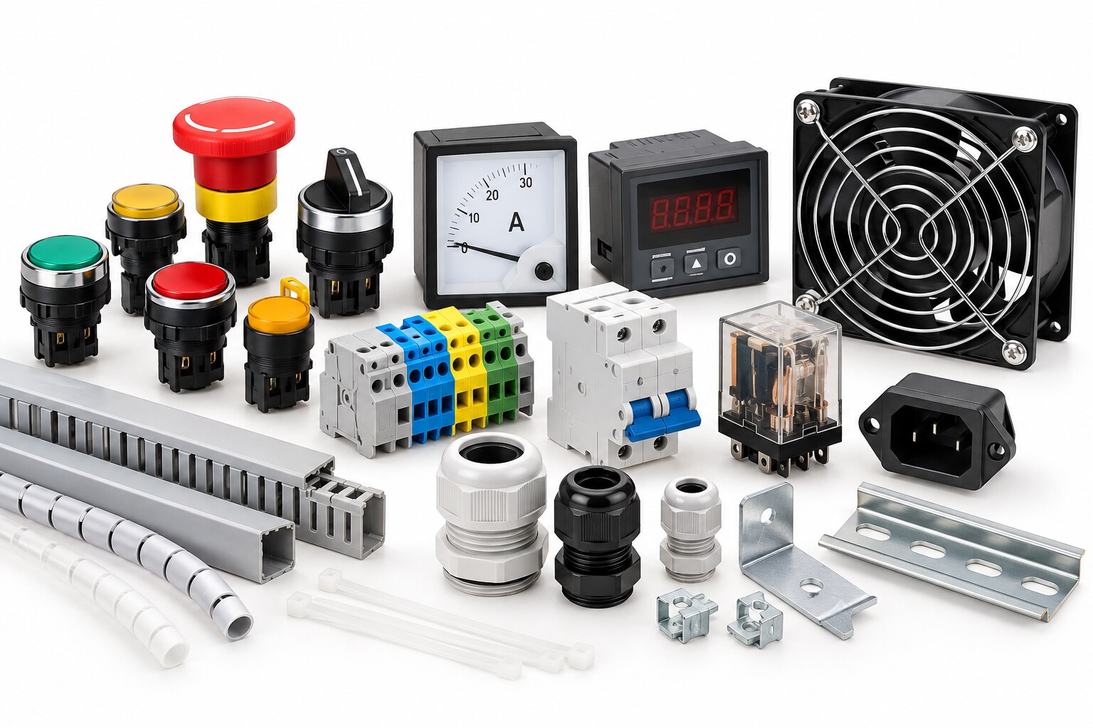
A safe control panel depends on more than breakers and a metal enclosure: heat, fault current, wiring access, grounding, ingress protection and maintenance labels all affect the finished assembly. Use the checklist below to decide what belongs in your panel, place each device correctly and verify that the selected accessories work together rather than merely fitting in the enclosure.
Key takeaways
- Use a lockable disconnect; a stop pushbutton does not provide isolation.
- Calculate enclosure heat before wiring, then leave space for inspection and service.
- Select protection using load current, fault current and coordination requirements.
- Seal cable entries and verify labels, compatibility, SCCR and bonding hardware.
Build the panel around safety, access and maintenance
Safety hardware is essential in nearly every industrial control panel: a lockable disconnecting means, protective-bonding hardware, clearly identified terminals, and durable circuit labels. A stop pushbutton does not replace isolation. Mark each disconnect by its actual load or circuit, not merely “breaker” or “motor,” and include the panel SCCR on the nameplate.
Use this control panel accessories checklist before approving the layout:
- PE terminal blocks sized for the protective-bonding conductor and prospective fault current.
- Door-bonding straps or bonding jumpers across painted, hinged and removable metal parts.
- DIN rail terminals, end stops, separators and markers that keep wiring identifiable during maintenance.
- Wire duct, strain relief and cable-entry hardware that prevent conductors from rubbing or pulling on terminals.
- A nameplate showing the panel identification, supply information and SCCR required by the applicable code.
| Accessory | Status | When it applies |
|---|---|---|
| Disconnecting means | Essential | Every panel requiring safe supply isolation; provide identification and access for lockout |
| PE terminal blocks and door-bonding straps | Essential | Any enclosure with exposed conductive or removable metal parts |
| SPD, auxiliary contacts or surge monitoring | Application-dependent | Where lightning, switching transients, remote status or sensitive electronics justify them |
| Fan, filter, heat exchanger or air conditioner | Application-dependent | Only after calculating heat load and matching the cooling method to dust, oil, washdown and enclosure rating |
| Spare terminals and duct capacity | Recommended | When future circuits or maintenance changes are likely |
Arrange components and calculate cooling before wiring
Place heat-producing devices low and keep heat-sensitive equipment out of their rising-air path. Mount drives, transformers, power supplies, contactors and braking resistors with their specified clearances; position PLCs, relays and communication modules away from these sources.
Separate power wiring from control wiring with ducts, and leave terminal blocks, breakers and bus bars accessible for testing and replacement.
- List the heat losses from drives, power supplies, transformers, contactors, relays and wiring—not only the largest device. Add the watts shown on datasheets, then calculate airflow with Q = 3.1 × total watts ÷ allowable temperature rise in °C, giving Q in m³/h.
- Use that result as required airflow, not the fan’s free-air rating. Select enclosure fan sizing after allowing for filter loading, grille resistance and the difference between the enclosure’s internal temperature and the ambient temperature.
- Provide a filtered intake and a high exhaust path so air crosses the hot components. A fan without a controlled air path can compromise the enclosure’s IP or NEMA protection.
- Add thermostat control to start cooling at a chosen internal temperature and prevent continuous fan operation. Confirm the fan’s supply voltage, noise, service access and filter replacement space.
- Reject a basic fan in dusty, oily, washdown or high-ambient locations. Use a sealed heat exchanger or enclosure air conditioner when filtered ventilation cannot maintain temperature without exposing the panel interior.
Select protection by load, fault current and coordination
Choose protective devices against load current, conductor ampacity, prospective fault current and coordination—not ampere rating alone. MCB selection must also account for inrush; a breaker sized too close to motor starting current can nuisance-trip, while one above the conductor rating leaves wiring exposed.
| Device | Check before selection | What goes wrong if mismatched |
|---|---|---|
| MCB | Load, conductor ampacity, inrush and interrupting rating | Nuisance trips or unprotected conductors |
| MPCB | Motor nameplate FLA, starting method and branch fault level | Failed starts or inadequate motor protection |
| Fuse or branch breaker | Available fault current and documented SCCR combination | The panel’s short-circuit rating becomes invalid |
MPCB selection does not replace motor overload protection when the motor circuit requires a separate overload relay. Set the overload to the motor nameplate data and verify that the short-circuit protective device, contactor and overload are a permitted combination.
For a control transformer or power-supply output, check inrush, conductor ampacity, source fault current and the manufacturer’s specified fuse or breaker.
Panel SCCR is the rating of the complete power circuit, not the main breaker’s interrupting rating. Mark it at the panel under NEC 409.110, and ensure it equals or exceeds the available fault current at the panel terminals.
Under UL 508A Supplement SB, replacing a documented breaker or fuse with a similar ampere rating can invalidate the tested combination.
- Record the available fault current.
- Verify every branch component’s rating and coordination.
- Check feeder terminals, bus structures, contactors and overloads in the SCCR calculation.
Protect wiring, entries and enclosure boundaries
A panel’s protection ends at every joint, door and cable entry. Use PE terminal blocks, grounding studs and bonding jumpers to maintain continuity across painted or removable metal parts. Fit a door-bonding strap rather than relying on hinges, and size the protective bonding circuit for the prospective fault current under IEC 60204-1.
- Match each cable gland to the cable’s outside diameter, thread, enclosure material and environmental rating. Cable glands to IEC 62444 provide retention and sealing only when installed within their specified range.
- Select terminal blocks for conductor material, cross-sectional area, voltage, current and short-circuit conditions. Fit ferrules only when their dimensions suit the terminal’s permitted conductor-entry geometry.
- Size wire duct for the cable bend radius and planned additions, not its empty physical volume. Overfilled duct damages insulation and makes inspection difficult.
- Treat the enclosure, glands, gasket, breather, drain and mounting arrangement as one environmental barrier. A high IP or NEMA rating alone does not make a panel suitable for sunlight, condensation, corrosion, washdown chemicals or hazardous locations.
| Accessory | Check before installation | Failure prevented |
|---|---|---|
| PE terminal block | Fault-current and conductor ratings | Overheating during a fault |
| Cable gland | Seal, thread and cable-diameter range | Water entry or cable pullout |
| Bonding strap | Clean metal contact at both ends | Loss of door bonding |
| Ferrule | Correct fit in the terminal | Loose or damaged strands |
Verify compatibility, markings and the complete accessory package
Approve the assembled panel, not isolated catalogue parts. Before ordering, match each accessory to the device dimensions, voltage, current, conductor size, mounting method and enclosure environment; a component that fits the rail can still leave an unsafe termination or invalidate the documented SCCR.
1. Request the manufacturer’s datasheet, installation instructions and compatibility list. Confirm MCB shortlink compatibility by checking breaker series, pole spacing, busbar pitch, rated current and terminal design. Do not substitute a similar-looking link or protective device without updating the design record.
2. Record the specified breaker terminal torque and use a calibrated torque screwdriver during assembly. An under-torqued terminal heats up; an over-torqued terminal damages the clamp or conductor.
3. Compare NEMA versus IP rating against the installed environment, not marketing language. Check the enclosure, door gasket, cable glands, drain or breather, cooling method and mounting orientation as one system. A fan and filter can defeat the intended ingress protection.
4. Check every power-circuit component—terminals, contactors, overloads, bus structures and branch protection—against the panel SCCR. NEC 409.110 requires the industrial control panel’s SCCR and identification to be marked, while NEC 110.10 requires equipment to withstand the available fault current. The marked SCCR must meet the prospective fault current at the panel terminals.
5. Inspect the complete package for labels, ferrules, end stops, covers, spare terminals, bonding hardware and mounting clips. Dollex Control Panel Accessories can be included in the comparison, but verify each item against the receiving breaker or enclosure rather than assuming brand interchangeability.
Related products
 | Fans Panel fans are efficient cooling devices that use a flat, compact design to circulate air in tight spaces. View product → |
 | PUSH BUTTONS Dollex Control Panel Accessories Product Overview: The Push Button with Key from Dollex Control Panel Accessories is engineered for enhanced security... View product → |
Frequently asked questions
What safety accessories should every control panel include?
Use a lockable disconnecting means, protective-bonding hardware, identified terminals, durable circuit labels and an SCCR nameplate.
Why calculate cooling before wiring a control panel?
Heat from power supplies, drives and other components affects reliability, so calculate enclosure heat and choose ventilation or cooling before final layout.
How should you select circuit protection for a control panel?
Compare the load current, available fault current and required coordination before choosing breakers, fuses or other protective devices.
What should you check before energizing a control panel?
Verify accessory compatibility, terminal and circuit markings, bonding continuity, cable-entry seals, enclosure boundaries and the complete installed package.
Related products
 | The MCB Shortlink by Dollex Control Panel Accessories is designed for quick and secure interconnection of multiple MCBs. View product → |
 | Dollex Bus Bar Sleeves are designed to provide electrical insulation and mechanical protection for bus bars in control panels and switchgear... View product → |
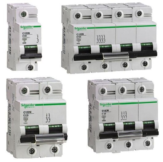 | MCBs At Dollex Control Panel Accessories, we offer a premium range of Miniature Circuit Breakers (MCBs) designed for superior protection and long-lasting... |
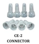 | The CE-2 connector is a versatile electrical component used for secure and efficient connections in various electronic devices. View product → |