An aluminium conductor can fit a lug by nominal size and still fail because its strand construction, barrel, crimp system, terminal interface or operating conditions do not match. By the end, you will have a practical checklist for specifying the lug, verifying its evidence and preparing a termination that fits both the cable and the equipment.
Key takeaways
- Match the lug to conductor class, strand arrangement and outside diameter.
- Check barrel dimensions, palm design and the aluminium-to-copper contact interface.
- Treat lug size and current rating as separate checks; request test evidence.
- Use the marked crimp system and inspect the completed termination for defects.
Match the lug to the conductor’s complete construction
A matching mm² number does not prove an aluminium cable lug fits the cable. Compare the lug’s approved conductor range with the cable cross-sectional area, conductor class, strand arrangement and actual conductor outside diameter.
A 120 mm² compacted Class 2 conductor does not have the same shape or strand packing as a 120 mm² flexible Class 5 conductor.
Check these details on the cable datasheet and lug marking before purchase:
- Conductor material: aluminium, copper, or a specified combination. An aluminium-alloy lug and a tinned copper lug are not interchangeable.
- Conductor class: solid conductor603? or stranded Class 2, Class 5 or Class 6. Confirm whether the lug is approved for compacted, non-compacted, sector-shaped or round conductors.
- Bare conductor diameter: measure or obtain the manufacturer’s figure, then compare it with the lug barrel’s stated internal diameter and insertion range.
- Insulation diameter and strip allowance: verify that the cable enters the barrel without forcing, excessive stripping or damage to the insulation.
- Installation geometry: check that the lug length and cable’s minimum bending radius fit the enclosure without twisting the crimp or loading the terminal.
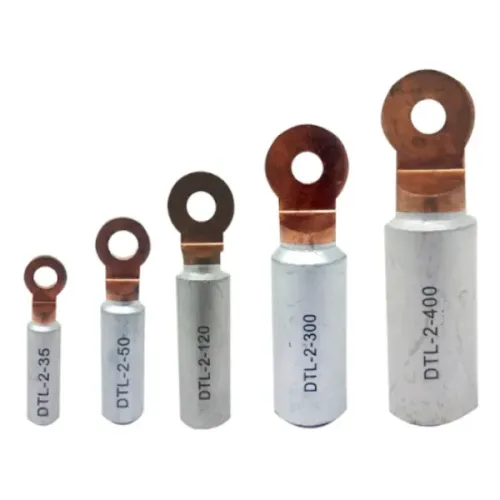
Do not choose a plain aluminium lug merely because the cable has aluminium strands. If its palm connects to copper, select a bi-metallic lug or an approved transition connector tested for that aluminium-to-copper interface; galvanic corrosion and thermal cycling can loosen an unsuitable joint.
Check the barrel, palm and aluminium-to-copper interface
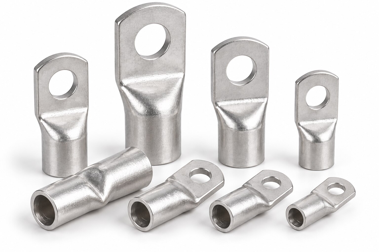
A lug can fit the conductor and still fail at the terminal. Check the barrel internal diameter and barrel length against the conductor’s actual outside diameter, construction and required insertion depth; a short barrel or oversized bore can produce a weak crimp.
| Connection type | Lug material | Check before selection |
|---|---|---|
| Aluminium-to-aluminium | Aluminium lug approved for the conductor | Confirm the barrel and terminal are compatible |
| Copper-to-copper | Copper lug | Match the barrel and palm to the copper conductor and terminal |
| copper-to-aluminium connection | Bimetallic lug or approved transition connector | Use the tested interface; do not bolt a plain aluminium palm directly to copper |
Measure the palm width and palm thickness against the terminal, busbar, breaker shroud and required clearances. Match the hole diameter and hole spacing to the hardware: an M8 stud needs the specified M8 hole, while an M10 stud needs the specified M10 hole. Check edge distances and palm orientation before ordering.
A correct hole pattern is not enough. Confirm that the palm fits without touching adjacent phases, and that the barrel entry, insulation diameter, bending space and cable minimum bending radius work inside the enclosure. Forcing a large cable into alignment with a short lug can load both the crimp and equipment terminal.
Use the terminal manufacturer’s torque value; hydraulic crimp pressure is not a substitute.
Separate lug size from current rating and demand test evidence
A lug marked Al 95–120 mm² does not automatically carry the cable’s allowable ampacity. Verify the installation rating separately, then confirm that the lug’s conductor range, current rating and temperature rating cover the result.
- Calculate ampacity using conductor material, insulation rating, installation method, ambient temperature, enclosure heating and grouping factor. Apply the equipment-termination temperature limit; a cable permitted to run hotter does not make a lower-rated lug acceptable.
- Check the lug’s stated continuous-current and operating-temperature limits against the calculated load, including continuous-duty loading and expected overloads.
- For fault-prone circuits, demand a test report showing short-circuit withstand and thermal cycling performance for the connector system, not just a catalogue current figure.
Require evidence that identifies the exact lug, conductor type and size, crimp system, test conditions and failure limits. IEC 61238-1 covers performance testing for compression and mechanical power-cable connectors; UL 486A-486B covers wire connectors and soldering lugs for copper and aluminium conductors.
A certificate that names only a product family, or a marking that shows only a size range, proves little. Check the certificate and test report together, including the fault-current duration and temperature class. If neither document addresses the installation’s aluminium conductor and duty, reject the selection or obtain written technical confirmation.
Read the marking and select the validated crimp system
Approve the lug, die and hydraulic crimping tool as one validated system, not as separate items. Match the manufacturer’s die code, crimp code, die cavity size, crimp profile, number of crimps and crimp sequence exactly; a visually similar die can leave a connection that passes inspection but fails electrically or mechanically.
Read the lug marking before installation. It must identify the conductor material, conductor-size range, applicable conductor class, approved crimp method and manufacturer traceability. Confirm that the marking covers the actual cable: a lug rated for a standard stranded conductor may not suit a compacted conductor, Class 5 flexible conductor or Class 6 extra-flexible conductor.
Use only the profile named by the manufacturer. A hexagonal crimp and an indent crimp are not interchangeable, and neither the tool’s hydraulic pressure nor a die from another product family proves a valid termination.
Require the manufacturer’s installation sheet, die code, crimp code, number and position of crimps, certification reference and any specified terminal torque.
- Reject the setup if the lug marking is missing, unreadable or inconsistent with the approved drawing.
- Record the lug batch or traceability reference, tool identification, die code and crimp code in the installation record.
- If you source through Dollex Control Panel Accessories, request this traceability and tooling information with the selected lug rather than accepting a generic size match.
Related products
 | Dollex Bimetallic Lugs are specialized electrical connectors designed for reliable joining of copper and aluminum conductors. View product → |
 | Dollex Copper and Aluminium Barrels are premium-quality connectors designed for efficient electrical cable termination and joining. View product → |
Follow the preparation sequence and inspect the finished termination
A selected aluminium lug is fitted correctly only when the conductor preparation, crimping, bolting and final checks match the manufacturer’s instructions.
1. Confirm the strip length before cutting insulation. Remove aluminium oxide by the specified brushing or preparation method, then apply joint compound only when the lug instructions require it. Do not substitute generic anti-oxidant paste for a specified treatment.
2. Push the conductor fully into the barrel to the stated insertion depth. Check that no strands are exposed beyond the intended barrel, the insulation enters cleanly, and the lug palm has the correct orientation for the terminal.
3. Fit the approved die and follow the specified crimp sequence. Keep every crimp in the marked crimp position; a misplaced first crimp can leave an uncompressed section or distort the palm.
4. Perform a visual inspection for cracks, severe barrel distortion, damaged palm surfaces, loose strands and incomplete crimps. Confirm that the finished cable route respects the cable’s minimum bending radius and does not twist or load the lug.
5. Tighten the bolted connection to the specified terminal torque using a calibrated torque tool. Hydraulic crimp pressure is not a torque setting; under-torque creates heating, while over-torque damages the contact.
6. Where the quality plan specifies acceptance values, use the manufacturer’s gauge or documented pull test and resistance test. A termination that looks sound can still have insufficient mechanical grip or excessive contact resistance.
Frequently asked questions
How do you match an aluminium cable lug to a conductor?
Compare the lug’s approved conductor range with the cable’s cross-sectional area, conductor class, strand arrangement and actual outside diameter.
What should you check on an aluminium cable lug’s construction?
Inspect the barrel dimensions, palm and terminal-hole design, and the aluminium-to-copper interface when joining dissimilar metals.
Does the lug’s mm² size prove its current rating?
No. Check the lug’s current-rating evidence separately and request test documentation for the intended conductor, temperature and installation conditions.
How do you select the correct crimp system?
Read the lug markings and use the die, tool, crimp sequence and conductor preparation method validated for that lug.
How do you inspect a completed aluminium lug termination?
Follow the preparation and crimp sequence, then check crimp location, compression, marking, surface condition, conductor insertion and signs of cracking or looseness.