A lug can fit a cable and still produce a poor industrial connection if its barrel, die, palm hole, conductor class or terminal hardware is mismatched. By the end, you will be able to specify the connection, prepare and crimp it correctly, tighten the terminal safely, and verify the result beyond a visual check.
Key takeaways
- Match lug barrel size to conductor area, material and construction.
- Use the crimping method specified for the lug and cable.
- Inspect the completed crimp for full insertion, damage and correct compression.
- Torque the bolted palm to the hardware manufacturer’s specified value.
How to match a copper cable lug to the conductor and terminal
Match the lug to the cable and terminal as a system, not by choosing a hole that happens to fit. Confirm the conductor cross-sectional area, conductor material, construction and terminal hardware before installation.
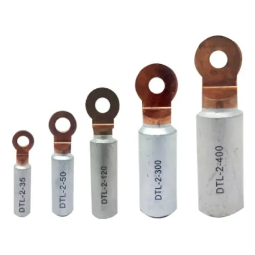
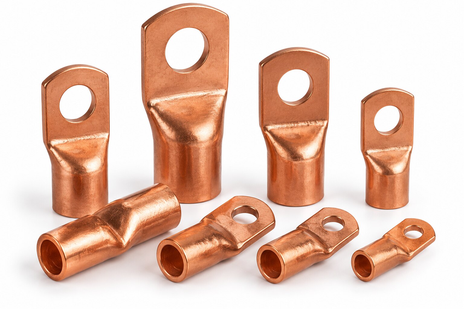
Copper cable lug selection starts with the marking on the barrel. Match its stated cable range, such as 16–25 mm², to the actual conductor cross-sectional area; the stripped conductor must enter fully without forcing or loose strands. Confirm that the lug is approved for copper, or for aluminum if that is the conductor.
A copper-only lug is not suitable for aluminum cable because oxide, creep and thermal expansion can degrade the joint.
| Marking or dimension | What to match | What goes wrong if ignored |
|---|---|---|
| Cable range, in mm² | Conductor cross-sectional area | An oversized barrel produces an unreliable crimp |
| Cu, Al, or Cu/Al marking | Conductor material | Oxide and creep can raise contact resistance |
| Class 5 or Class 6 approval | Stranded conductor class | Fine strands can flare, escape or be cut |
| Barrel inside diameter and length | Stripped conductor and insertion depth | Partial insertion reduces current-carrying area |
| Palm hole, such as M8 or M10 | Stud or bolt diameter | A loose hole permits movement and reduces bearing |
| Palm width and shape | Washer, busbar and terminal surface | The palm can bridge an insulating shoulder or curved surface |
Check the lug’s standard and system instructions, including UL 486A-486B where applicable. A listed lug, conductor range, die set or installation method cannot be substituted casually.
Which termination method fits the cable and the installation
Choose the termination by conductor construction, installation forces and maintenance access—not by cable size alone. The wrong method can loosen under industrial vibration, crack after thermal cycling or damage strands during installation.
| Option | Use it when | Wrong choice when |
|---|---|---|
| Compression lugs | The conductor and approved die system match, especially for permanent power-cable joints and high fault-duty circuits. | The cable is fine-stranded, flexible or aluminium without an explicitly approved lug and preparation method. |
| Mechanical shear-bolt lugs | You need a field-installed joint without a hydraulic crimper, and the lug is rated for the conductor range and fault duty. | The enclosure lacks bolt clearance, the connector cannot accommodate the conductor class, or the shear-bolt instructions are unavailable. |
| Soldered lugs | An equipment standard expressly specifies solder and the cable remains mechanically supported and free from repeated flexing. | The joint faces industrial vibration and thermal cycling; solder can wick into strands, create a rigid fatigue point and soften during abnormal heating. |
| Crimp terminals | Control wiring, smaller conductors or equipment designed for insulated or uninsulated terminal crimping calls for them. | You substitute them for a power lug, use the wrong barrel or crimp profile, or fit a bootlace ferrule where the terminal has no approval for that system. |
Support the cable before tightening any termination. Its weight, bend force and short-circuit movement must not load the lug palm or equipment stud.
For copper-to-aluminium work, use a connector marked for both metals and follow its oxide-removal, compound and torque instructions. A copper-only lug is not acceptable because the cable happens to fit.
How to prepare the conductor and make the specified crimp
A sound barrel starts with a clean, undamaged conductor. Strip only the length specified for the lug, using a tool that removes insulation without nicking strands; a single cut strand reduces the intended cross-section and creates a stress point. Do not tin the conductor unless the lug manufacturer explicitly permits it.
- Confirm that the lug, conductor material and crimp system match. Fine-stranded, Class 5 or Class 6 cable requires a lug and die approved for that strand construction; a standard lug can cut or flare the strands.
- Prepare the exposed conductor. Keep strands together, remove contamination, and brush aluminium oxide removal from an aluminium conductor with the method specified for the connector. Apply the approved joint compound immediately when the connector instructions require it. Never use a copper-only lug on aluminium cable.
- Open the calibrated crimp tool and install the specified die index and profile. Use a hex crimp die only when the lug data calls for hex compression; an indent or generic hydraulic die is not an equivalent substitute.
- Insert the conductor fully into the barrel until it reaches the stop or appears through the inspection window. The insulation must meet the barrel mouth without entering it, and the strip length must leave the specified unsupported transition.
- Position the die at the marked location, then make the stated number of complete compressions in the manufacturer’s stated sequence and direction. Keep the first crimp clear of the palm-to-barrel transition; partial closure or an extra crimp can damage strands.
Record the tool, die, crimp count and conductor identification for traceability.
How to verify the crimp and tighten the bolted palm
A neat hex shape does not prove a sound crimp. Check conductor visibility through the lug’s inspection window, or at the barrel end, to confirm that the conductor reaches the specified insertion depth. Look for even die marks, no split barrel, no displaced strands, and no crimp placed across the barrel-to-palm transition.
1. Compare the completed barrel with the tool manufacturer’s pattern. Confirm the crimp count and position, die identification, conductor size, and lug marking in the installation record. A mismatched die can produce convincing marks while leaving excessive resistance or weak strand compression.
2. Reject the lug if strands are cut, flared beyond the barrel, trapped outside the crimp, or visible gaps remain between conductor and barrel. Use the specified pull testing method when the termination standard or project specification requires it; a failed pull test identifies a barrel problem, not a loose palm joint.
3. Check the bolted palm separately. Clean the palm, busbar and contact surfaces, remove oxide or foreign material as the equipment instructions permit, and fit the specified washer and nut arrangement. Align the holes without forcing the lug sideways.
4. Tighten with a calibrated torque tool to the terminal, busbar or equipment manufacturer’s stated value and sequence. Never substitute a generic lug-barrel torque value. Over-torquing can warp the palm or strip threads; under-torquing permits movement and heating.
5. Record low-resistance testing across the completed connection when specified, identifying the test points. A good barrel with a poor palm can pass pull testing yet fail the joint resistance check.
How installation conditions, standards and records protect connection life
A lug is only as reliable as the installation surrounding it. Account for current cycling, short-circuit forces, ambient temperature, humidity, chemical exposure and vibration, then support the cable so its weight, bend radius or repeated movement cannot load the palm or equipment terminal.
IEC 61238-1-1 evaluates compression and mechanical connectors through resistance, temperature-rise, mechanical and short-circuit tests for power cables up to 1 kV AC or 1.5 kV DC. UL 486A-486B covers wire connectors and soldering lugs for copper and aluminium conductors; follow the listed conductor range, die, material and installation method rather than treating approval as universal.
Tin-plated copper lugs help control humidity-related and dissimilar-metal corrosion, but scratched plating, trapped moisture and a dirty busbar still raise contact resistance. Match the palm to the terminal design: use the specified stud, washer arrangement and contact area, and prevent vibration from loosening the joint.
Provide mechanical support independently of the termination. Dollex Control Panel Accessories’ steel cable ties can secure a cable to its tray when installed without crushing insulation or transferring movement into the lug.
Keep inspection records that identify:
- lug part number, conductor size and material;
- crimp die or shear-bolt method and installer;
- calibrated torque wrench setting, date and connection location;
- visual inspection, resistance or thermal findings, and corrective work.
A low initial resistance reading proves little; compare temperatures under similar load after current cycling or maintenance, because corrosion, creep and strand damage can develop later.
Related products
 | Dollex Bimetallic Lugs are specialized electrical connectors designed for reliable joining of copper and aluminum conductors. View product → |
 | Dollex Copper and Aluminium Barrels are premium-quality connectors designed for efficient electrical cable termination and joining. View product → |
Frequently asked questions
How do you match a copper cable lug to a conductor and terminal?
Check the conductor cross-sectional area, material, construction and lug barrel range. Confirm the palm hole fits the terminal bolt without relying on hole size alone.
Which termination method fits an industrial cable installation?
Use a compression lug with the specified die and crimp pattern when the lug and cable are designed for crimping. Choose the termination method that matches the conductor construction, available tooling and installation conditions.
How do you prepare and crimp a copper cable lug?
Strip insulation without nicking strands, clean the conductor when required, insert it fully into the barrel and make the specified crimps with the correct tool and die.
How do you verify a crimped lug and tighten its bolted palm?
Check conductor insertion, crimp position, barrel deformation and signs of strand damage. Install the palm with compatible hardware and tighten it to the specified torque.
How do installation conditions and records protect connection life?
Account for moisture, corrosion, vibration, temperature and available clearance. Record the lug, cable, crimp tool, die, inspection result and final torque for maintenance traceability.