
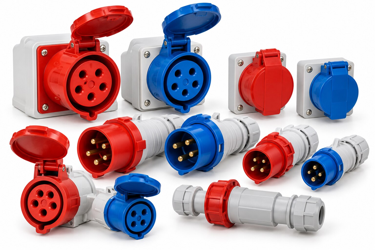
A current label such as 63A does not tell you whether a connector suits your load, cable, environment or supply. By checking electrical ratings, pole arrangement, earthing, ingress protection, materials and termination details in the right order, you can specify a complete mated assembly that will operate safely in service.
Key takeaways
- Size the connector from continuous load, startup current and cable capacity.
- Match pole count, voltage, frequency and earthing system before ordering.
- Specify the IP rating for the complete mated connection, not one component.
- Check materials, terminations and the finished assembly against site conditions.
Start with the Load, Supply and Cable
A 63A label identifies the connector’s rated current; it does not prove that your installation can carry 63A continuously. Start with the equipment nameplate and measure the expected continuous load, then account for startup current from motors and inrush current from transformers, capacitors or power supplies.
A brief peak can require a different connector, protective device or cable than the running current suggests.
Before choosing the connector, verify:
- The continuous load, startup current, inrush current and duty cycle against the connector’s rated current.
- The conductor cross-section, insulation temperature rating, cable length, voltage drop and installation method against the manufacturer’s table.
- Ambient temperature and temperature rise inside the enclosure; heat reduces the usable current even when the connector is marked 63A.
- The circuit breaker or fuse’s trip characteristics and breaking capacity, so the protective device coordinates with the cable and connector.
- The supply voltage, number of phases and frequency from the installation documentation, not from the current marking alone.
IEC 60309 classes commonly include 16A, 32A, 63A and 125A. Select the next suitable rating only after checking the complete circuit; a larger plug does not compensate for an undersized cable or poorly coordinated protection.
For outdoor equipment, confirm the housing, seal and cable jacket’s UV and low-temperature range. Match the gland to the cable’s actual outside diameter and construction. An incorrect entry can transfer pulling force to terminals, damage the seal and create intermittent heating at the contact.
Match Poles, Voltage, Frequency and Earthing
A connector can fit mechanically and still be electrically wrong. Check the marking for pole count, rated voltage, frequency, clock position and earthing arrangement; do not approve a replacement from its current rating or colour alone.
Select the pole arrangement for the conductors the equipment actually needs:
| Arrangement | Conductors provided | Typical application |
|---|---|---|
| 2P+E | Line, neutral and protective earth | Single-phase equipment requiring an earth |
| 3P+E | Three phases and protective earth | Three-phase motors or heaters without a neutral |
| 3P+N+E | Three phases, neutral and protective earth | Three-phase plus neutral and earth equipment |
A five-pin connector is appropriate for 3P+N+E. A four-pin connector normally serves 3P+E, while a six-pin or other configuration applies only when the equipment requires additional dedicated contacts. Never leave the protective-earth contact out as a pole-saving measure.
IEC 60309-2 uses mechanical keying and earth-contact clock position to distinguish voltage and frequency combinations. Match that clock position, the voltage marking and the frequency marking to the supply; a connector’s blue or red colour does not prove compatibility.
After connecting three-phase equipment, verify phase rotation at the load. A correctly keyed plug cannot detect two phases reterminated upstream, and a motor, pump or compressor can run backwards. Confirm the socket, plug, cable conductors, terminal markings and upstream protection all support the selected neutral and protective-earth arrangement.
Specify IP Protection for the Complete Connection
Specify the IP rating for the complete mated connection, including plug, inlet, cable gland, gasket and cover, not just the plug body. An incorrectly sized cable, loose gland, damaged seal or unlatched cover can reduce a marked IP65 assembly to a leak point. Ask for the assembled rating and installation instructions.
| Rating | Protection | Suitable exposure |
|---|---|---|
| IP44 | Protection from solid objects above 1 mm and splashing water | Light rain and sheltered areas; not dust-tight or suitable for washdown |
| IP54 | Limited dust ingress and protection from splashing water | General industrial areas and light rain; not hose-jet protection |
| IP65 | Dust-tight and protected against water jets | Dusty locations and specified washdown conditions |
| IP67 | Dust-tight and protected against temporary immersion | Flood risk or accidental submersion; not automatically suitable for jet washing |
Match the code to the actual water exposure. Under IEC 60529, IPX5 covers water jets, IPX6 covers powerful jets, IPX7 covers temporary immersion and IPX8 covers continuous immersion under manufacturer-specified conditions. An IP67 connector does not automatically meet jet-wash requirements unless it also carries IPX5 or IPX6.
IP protection does not prove impact resistance or hazardous-area approval. Specify an IK rating under IEC 62262 where dropped tools or vehicles threaten the connection, and use IEC 60079-14 selection rules for explosive atmospheres. For outdoor use, verify UV suitability, low-temperature limits, seal performance and cable-jacket flexing; do not infer them from the IP code.
Choose Materials for Heat, Chemicals and Mechanical Abuse
A connector that survives a dropped tool can still fail outdoors when UV exposure cracks its seal or low temperature makes the cable jacket stiff. Compare the whole assembly—housing, gasket, contacts, gland and cable—not the body material alone.
| Material | Strengths | Check before specifying |
|---|---|---|
| Rubber | Flexible under vibration and repeated flexing; good shock absorption | Confirm operating temperature, UV exposure and chemical resistance. Welding spatter can burn it, while oils, solvents and disinfectants can swell it. |
| Thermoplastic | Lightweight, corrosion-free and economical; suitable for many general industrial installations | Verify the resin’s temperature range and UV stability. Hot surfaces, welding spatter and concentrated chemicals can soften or embrittle it. |
| Nylon | Tough, electrically insulating and resistant to impact and many oils | Check the exact nylon grade, moisture absorption, low-temperature performance and compatibility with acids, caustics and cleaners. |
| Metal-bodied | Handles impact, abrasion and welding spatter better than plastic; useful near machinery | Specify corrosion protection and inspect the cable entry. Vibration can loosen poorly secured metal assemblies, and bare metal can corrode outdoors. |
| Stainless steel | Best choice for severe washdown, corrosion and hygienic areas when correctly specified | Select the grade and finish for the chemical exposure; 316 does not remove every chloride risk. Confirm seals, contacts and cable-jacket compatibility. |
Treat impact separately from ingress: IPX5 or IPX6 describes water jets, while an IK impact rating under IEC 62262 addresses mechanical impact. For vehicle traffic, dropped tools or persistent vibration, request the declared IK rating and a retention system. Specify the chemical, concentration, temperature and exposure time, then verify the housing and seal data.
Compare Terminations and Verify the Finished Assembly
Choose the termination for the conductor, vibration level and maintenance method—not for convenience alone. Screw terminals need the specified torque and a conductor that cannot loosen under vibration. Spring terminals maintain contact pressure as copper expands and contracts.
Cage-clamp terminals suit repeated wiring work when the conductor is fully inserted, while crimp contacts require the correct contact, strip length and calibrated crimp tool.
| Option | Strength | Main assembly risk |
|---|---|---|
| Screw terminals | Direct, inspectable clamping | Loose torque or stranded wires cut by overtightening |
| Spring terminals | Resists vibration and thermal cycling | Incomplete insertion gives a false connection |
| Cage-clamp terminals | Fast, repeatable conductor retention | Wrong ferrule length prevents full clamping |
| Crimp contacts | Reliable in plugs and disconnects | Wrong die or contact size creates pull-out and heating |
Match the gland to the cable’s actual outside diameter and construction. An oversized entry leaks and lets the cable move; an undersized one damages the jacket or seal. Tighten the gland to its instructions, secure the cable before the terminals carry any pull, and check that the gasket, cover, latch and mating inlet are undamaged.
- Verify conductor strip length, terminal markings, protective-conductor continuity and crimp pull-out resistance where specified.
- Inspect for exposed copper outside the terminal, crushed insulation, loose strands and a gland that turns with the cable.
- Record torque, contact type and cable diameter in the assembly check sheet.
Dollex Control Panel Accessories can be compared on these installation details rather than by current rating alone.
Related products
 | Plug & Socket The 63A 5PIN Plug & Socket are robust electrical connectors designed for high-current applications. View product → |
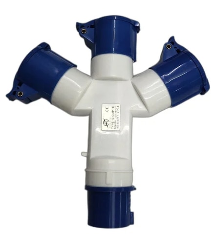 | Dollex presents Trishul Sockets, designed for safe and reliable electrical connections in residential, commercial, and industrial settings. View product → |
Frequently asked questions
How do you select an industrial plug and socket for the load?
Start with the equipment nameplate and expected continuous load. Check motor startup or transformer, capacitor and power-supply inrush, then confirm the plug, socket, cable and protective device can carry the demand.
How do pole count, voltage, frequency and earthing affect selection?
Match the pole configuration to the live, neutral and protective-earth conductors. Confirm rated voltage, frequency and earthing arrangement, and do not mate connectors with incompatible keying or ratings.
What IP rating should an industrial plug and socket have?
Choose an IP rating for the complete mated connection, including the cable entry, cover, gasket and enclosure. IP44 suits protection from solid objects and splashing water; higher ratings are needed for dust, jets or temporary immersion.
Which materials and terminations suit demanding environments?
Compare contact and housing materials against heat, chemicals, impact and abrasion at the installation site. Select screw, crimp or spring terminations based on conductor type, vibration and inspection access, then verify the completed assembly.


