A machine part reaches a defined point, moves a switch actuator, and changes an electrical contact that the control system can use to stop, start, reverse, or permit the next operation. By the end, you will be able to choose the right contact arrangement and actuator, wire the switch correctly, and recognise when a limit switch is unsuitable for accurate positioning or personnel safety.
Key takeaways
- Use normally closed contacts when a broken wire must trigger a fault.
- Match actuator overtravel and reset action to the machine’s stopping distance.
- Choose proximity or encoder sensing when contact, wear, or precision makes a limit switch unsuitable.
- Wire the switch into a control rung that removes motion power at the travel limit.
What happens when a limit switch changes machine motion?
A limit switch converts movement into a discrete electrical command: a machine part reaches a defined machine position, presses the actuator, and shifts the internal contacts.
The control circuit reads that change and can remove power to stop travel, energise the next actuator to start a step, command reverse travel, or permit motion that was previously blocked.
The limit switch operating sequence is mechanical first and electrical second. The cam or moving part must reach the operating position; the actuator then moves through its pretravel until the contacts change.
Drive inertia, PLC scan time, output delay and braking distance can carry the machine beyond that point, so the switch is not a position measurement or a substitute for a physical stop.
Contact arrangements determine what the circuit sees:
- Normally open (NO): the circuit is open at rest and closes when actuated, creating a “reached” signal.
- Normally closed (NC): the circuit is closed at rest and opens when actuated; this removes permission to run.
- Changeover: a common contact transfers from NC to NO, providing both states for sequencing or interlocking.
For a stop or permissive that must respond to a broken wire or lost control power, an NC, de-energise-to-run arrangement exposes that fault by removing permission. Mechanical bounce can create several transitions, so apply an input filter, timer or software debounce only after including its added delay in the stopping-distance calculation.
How should you match the actuator to travel and stopping mechanics?
Choose an actuator whose travel and approach direction let the machine trigger the switch before the switch becomes the physical stop. Leave stopping distance for inertia, drive delay and control response.
| Actuator style | Suitable approach | Main check |
|---|---|---|
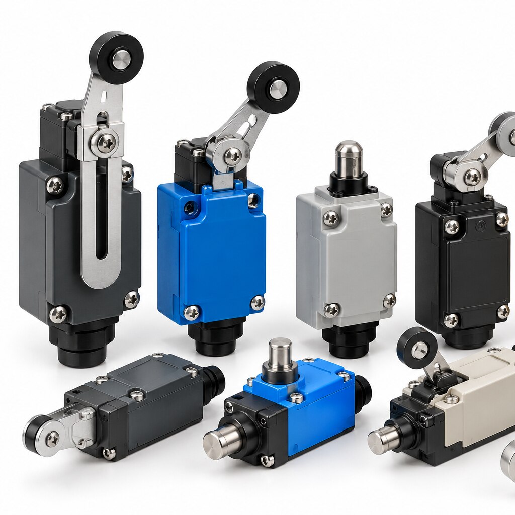
| Plunger actuator | Straight-on contact | Keep the machine aligned with the plunger axis |
| Roller plunger | A cam or flat surface moving straight across | Confirm the cam does not scrape or side-load the roller |
| Roller lever | Lateral approach along a cam edge | Check the permitted approach direction and speed |
| Adjustable lever actuator | Changing approach angle or contact position | Set the lever without exceeding its force or travel limits |
Compare the machine’s motion with the datasheet’s pretravel, operating position, overtravel, total travel and differential travel. Set the cam to reach the operating position with usable overtravel remaining; never rely on the switch’s overtravel to stop the machine.
Excessive switching force, speed or a lever held continuously against its stop will bend the actuator and alter repeatability.
Use a rigid mounting arrangement that matches the mounting-hole pattern. A flexible bracket or loose fastener changes the trip point under vibration. Before release, verify:
- The cam reaches the operating position at the slowest and fastest approach.
- The switch remains clear of the machine’s mechanical end stop.
- The IP rating suits dust, washdown, oil or coolant exposure.
- The ambient temperature stays inside the specified range.
- Differential travel does not permit unwanted cycling near the trip point.
When is a limit switch the wrong position-sensing technology?
A basic limit switch provides discrete threshold sensing: the actuator has reached one defined point, not where it is along the rest of its travel. Choose another technology when inertia, PLC delay, mechanical play, vibration or actuator wear makes that threshold too uncertain, or when contact wear and contamination threaten reliability.
For a practical limit switch comparison, match the sensing method to the decision you need:
| Option | Choose it when | Main advantage |
|---|---|---|
| proximity sensor | The target is metal and you need non-contact detection in dust, oil or repeated high-cycle motion. | No actuator contact, with better repeatability than a roller switch. |
| photoelectric sensor | You need to detect non-metallic objects, gaps, labels or a position across a longer distance. | Detects without touching the target; alignment and blocked lenses become failure points. |
| encoder | You need continuous position, speed or distance feedback rather than one end-of-travel signal. | Measures movement throughout the stroke, supporting precise positioning and stopping. |
| magnetic reed switch | A magnet is built into a cylinder, slide or door and low-force, sealed switching is sufficient. | Simple presence detection without mechanical actuation; magnetic alignment and contact bounce still matter. |
Use a mechanical switch when the machine needs a robust, unmistakable physical threshold and the actuator can tolerate impact. Do not use it for tight positioning: repeatability shifts with approach direction, cam geometry, mounting deflection and temperature. A switch also cannot report position between its trip points.
How do you wire a limit switch into a control circuit?
Wire the switch as a signal device unless its contact rating explicitly covers the load. For a PLC input, route the input supply through the contact and match the connection to the PLC’s sourcing sinking logic; the wrong arrangement leaves the input permanently on or off.
- A normally open NO contact closes when the actuator moves. Use it to announce “at position,” start a sequence, or energise a relay coil when movement occurs.
- A normally closed NC contact opens when the actuator moves or when a wire breaks. Use it for a basic de-energize-to-trip motor-control interlock, so loss of continuity removes the contactor command.
- A changeover contact provides one common terminal, one NO path, and one NC path. Use it when one position must enable one circuit while disabling another, or when you need a PLC input plus a relay signal.
Do not run a motor through a small switch. Drive a contactor or interposing relay, then verify the switch’s utilization category: AC-15 covers control of electromagnetic AC loads, while DC-13 covers electromagnetic DC loads.
A DC solenoid or contactor is an inductive load; use the specified lower current limit and suppression such as a diode for DC or an RC network for AC. Dollex Control Panel Accessories models should be selected by terminal arrangement, actuator travel, and documented AC-15 or DC-13 rating—not headline amperes.
Contact bounce can create multiple PLC transitions. Apply input filtering, a timer, or software debounce, then include that delay in the stopping-distance calculation.
Related products
 | Dollex ME-Type Limit Switches are compact, precision-engineered devices ideal for detecting mechanical movement and position in automation and... View product → |
 | Dollex presents the YBLX-ME/8108 Limit Switch, engineered for precise position detection and reliable operation in industrial applications. View product → |
When does a limit switch provide a fail-safe function?
A fail-safe limit switch is appropriate only when a fault drives the machine toward a defined safe state, not when the contact merely sequences a routine process. For crushing, guard access or hazardous motion, design the complete safety function: sensing, logic, actuation and stopping performance.
1. Define the hazard and safe response. Decide whether opening a guard must prevent starting, stop motion, remove stored energy or block restart. Calculate stopping time and distance, then specify the required performance level or SIL for the function, including the emergency stop performance level where relevant.
2. Choose a safety-position switch with positive opening IEC 60947-5-1 action when opening the contacts must be mechanically forced by actuator movement. A conventional NC limit switch is not positive opening unless its marking and documentation say so.
3. Use a de-energize-to-trip circuit. An NC circuit exposes a broken wire or loose terminal as a trip condition, but it will not detect welded contacts, a jammed actuator or a bypass.
4. Add redundancy and fault monitoring where the risk assessment requires them. The switch’s contact arrangement alone does not establish the required performance level or SIL.
5. Validate the installed function. Test guard opening, approach speed, vibration, temperature, stopping distance and restart prevention; then record the result and schedule proof testing.
A loose bracket or misaligned cam can defeat a correctly selected device. Treat mounting, diagnostics and test intervals as parts of the safety system, not installation details.
Frequently asked questions
What happens when a limit switch changes machine motion?
The machine part moves the actuator, changing the switch’s internal contacts. A control relay, PLC input, starter, or safety circuit then stops, reverses, slows, or permits motion according to the wiring and program.
How should you match the actuator to travel and stopping mechanics?
Select an actuator that reaches its operating point before the machine’s hard stop and has enough overtravel for stopping variation. Check roller direction, plunger force, reset travel, repeatability, and the manufacturer’s mechanical life rating.
When is a limit switch the wrong position-sensing technology?
Use a proximity sensor when physical contact is undesirable, an encoder when you need continuous position or speed feedback, or a safety-rated device when personnel protection requires monitored safety performance.
How do you wire a limit switch into a control circuit?
Identify the common, normally open, and normally closed terminals, then wire the selected contact into the PLC input, relay coil, contactor circuit, or interlock chain. Test the actual de-energised and actuated states before connecting machine power.
When does a limit switch provide a fail-safe function?
A limit switch supports fail-safe detection when its normally closed contact opens on the limit condition and also opens if the wire breaks or control power is lost. Use a properly designed safety circuit and safety-rated components when risk assessment requires them.
Related products
 | The WLCA-Series Limit Switch by Dollex is designed for accurate position detection and reliable mechanical performance in industrial automation. View product → |
 | The YBLX-ME/8104 from Dollex Control Panel Accessories is a high-precision limit switch designed for accurate position detection in industrial... View product → |
 | The YBLX-K3/20S/T from Dollex Control Panel Accessories is a compact, high-precision limit switch designed for reliable mechanical position sensing. View product → |
 | Dollex offers CNTD Model Limit Switches, engineered for precise position sensing and control in industrial automation systems. View product → |