Choosing switchgear by ampere rating alone can leave you with the wrong interrupting capacity, nuisance trips, poor fault coordination or an unverified panel. By the end, you will be able to match devices and ratings to the load, available fault current, operating duty, maintenance method and completed assembly.
Key takeaways
- Define the complete assembly, including enclosure, busbars, wiring and protective circuits.
- Check voltage, continuous current and short-circuit ratings at the installation point.
- Match breakers, fuses and relays to both load behaviour and fault conditions.
- Coordinate trip settings and maintenance access before commissioning the panel.
Define the Assembly Before You Compare Devices
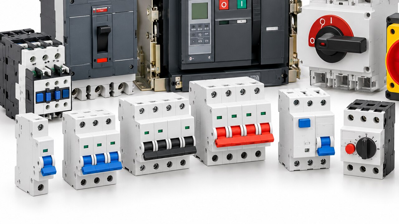
Switchgear means the complete arrangement used to switch, isolate, protect, control and distribute electrical power. You are not choosing a circuit breaker in isolation. You are specifying an assembly containing circuit breakers, fuses, isolators, busbars, terminals, contactors, overload relays, metering devices and protection relays, plus the enclosure, wiring and protective circuits that connect them.
| Term | What you are choosing | What it does not prove |
|---|---|---|
| Switchgear | Power switching, isolation, distribution and fault-clearing equipment | That one breaker’s certificate covers the completed assembly |
| Protective devices | Fuses, circuit breakers, overload relays and protection relays matched to faults or loads | That the devices provide selective coordination together |
| Controlgear | Contactors, motor starters, control relays and associated switching equipment | That it can interrupt the installation’s prospective short-circuit current |
| Switchboard versus control panel assembly | A switchboard primarily distributes power; a control panel assembly primarily operates, monitors and controls equipment | That either description alone establishes its voltage, temperature-rise or short-circuit rating |
Specify the finished assembly, including its rated voltage, current, short-circuit withstand, enclosure protection, internal separation, access and installation environment. A densely packed panel cannot automatically carry the nameplate current of each device; ambient temperature, ventilation, conductor grouping and rated diversity factor affect temperature rise.
For a low-voltage assembly, IEC 61439 separates the switchgear manufacturer’s design verification from the assembler’s routine verification. Confirm the completed panel’s temperature rise, clearances, creepage distances, IP rating, short-circuit withstand and protective-circuit continuity. A component type-test certificate alone does not validate the panel.
Verify Voltage, Current and Short-Circuit Ratings at the Installation Point
At the installation point, confirm that the completed assembly’s ratings exceed the system demands, not just the ratings printed on its incoming breaker. Record the supply voltage, frequency, phase arrangement, prospective short-circuit current and expected load current at that location.
| Rating | What to verify | Where to verify it |
|---|---|---|
| Rated operational voltage Ue | Device operating voltage matches the circuit voltage | Device data sheet and panel schematic |
| Insulation voltage Ui | Insulation rating exceeds the system’s maximum working voltage | Manufacturer documentation |
| Impulse withstand voltage Uimp | Assembly withstands the installation’s transient overvoltage category | Assembly verification records |
| Continuous current rating In | Assembly rating covers load current after derating | IEC 61439 data and temperature-rise verification |
| Icu and Ics | Breaking capacity covers prospective fault current at the stated voltage | Breaker test data and coordination tables |
| Icw | Short-time withstand current suits the protection and delay settings | Assembly verification and protection study |
Obtain the prospective fault current from a short-circuit study, utility data or a calculation using transformer impedance and conductor length. Compare it with Icu at the exact voltage, frequency and pole configuration; do not substitute Icw, or assume Ics equals Icu.
A series-rated combination counts only when the manufacturer documents that exact device pair and installation condition.
For an IEC 61439 assembly, demand both the manufacturer’s design verification and the assembler’s routine verification. Check temperature rise, short-circuit withstand, clearances, creepage, IP rating and protective-circuit continuity. The weakest verified busbar, terminal, contactor, disconnector or feeder path sets the assembly limit.
Match the Protective Device to the Load and Fault Condition
Choose the protective device from the load’s starting current, continuous current, conductor size and prospective fault condition—not from ampere rating alone. A motor that starts at six times full-load current can nuisance-trip an unsuitable breaker, while a fault beyond the device’s interrupting capacity can destroy it.
| Device | Use it when | Selection point |
|---|---|---|
| MCB | Protecting final circuits and small control loads | Match In to the cable; choose B, C or D curves for the measured inrush |
| MCCB | Protecting feeders, mains and higher-current equipment | Specify adjustable overload and instantaneous settings where coordination requires them |
| MPCB | Protecting an individual motor branch | Set overload to motor nameplate current; verify its short-circuit rating and starter coordination |
| Fuse | You need fast, current-limiting fault protection or high fault duty | For fuses versus circuit breakers, compare clearing time, replacement needs and selectivity |
| Motor-protection relay | Monitoring overload, phase loss, stall or imbalance in a motor starter | Pair it with a contactor and upstream short-circuit device; the relay does not clear a bolted short circuit |
Select poles to match the conductors you must isolate. Use one pole for an unshared line, 1P+N when the neutral is switched with the phase, three poles for a three-phase load, and four poles when the neutral also requires isolation.
A “neutral pole” must not be treated as an independently protected phase unless the device is specifically rated for that function.
Verify B C D curves against inrush, then check time-current curves or manufacturer tables for selective coordination. A series-rated combination is valid only for the exact tested devices, voltage and fault level. For motors, confirm the manufacturer’s Type 1 or Type 2 coordination table.
Coordinate Protection Without Creating New Operating Risks
Make the downstream device clear the fault before the upstream device, but prove that sequence at the actual prospective fault current. Discrimination selectivity requires time-current curves or the manufacturer’s selectivity table; different ampere ratings alone do not prevent an upstream instantaneous or short-time trip. Check magnetic thresholds, short-time delays and current-limiting behaviour together.
Residual-current protection must match the load waveform:
| Type | Detects | Use and risk |
|---|---|---|
| Type AC | Sinusoidal residual AC | Simple linear loads; unsuitable where pulsating or smooth DC can occur |
| Type A | AC and pulsating DC | Single-phase electronic loads; verify compatibility with the equipment |
| Type F | Mixed-frequency residual current | Certain single-phase variable-speed drives |
| Type B | Smooth DC and higher-frequency components | Drives, UPS systems, PV inverters and EV equipment |
- Select motor contactors by duty, not motor current alone. AC-1 covers resistive duty; AC-3 covers starting and stopping squirrel-cage motors. Plugging, inching, frequent starts and regenerative drives require the manufacturer’s stated utilization category and rating.
- Match the starter’s Type 1 or Type 2 coordination table to starting current, overload setting, prospective fault current and every starter component. Type 1 can require repair; Type 2 allows only easily separable contact welding.
- Treat added selectivity delay as an arc-flash decision: validate incident energy and use zone-selective interlocking, maintenance-mode instantaneous protection, current limitation or remote switching where needed.
- Use backup protection or cascade protection only for the exact tested upstream/downstream combination, voltage and fault level. Confirm the downstream assembly’s IEC 60947-2“Icw” and documented combination rating; never infer it from individual device ratings.
Confirm the Completed Panel, Environment and Maintenance Arrangement
You know the selection works only after the assembled panel passes verification as a system, not because each breaker or contactor carries an individual certificate. Check the documented IEC 61439 design verification for the assembly, then complete the assembler’s routine verification before energisation.
Record the conditions that shaped the design: ambient temperature, enclosure layout, ventilation, conductor grouping and rated diversity factor. The verified temperature rise and manufacturer derating data govern continuous loading; adding devices at their nameplate currents can overheat a crowded enclosure.
Confirm each of these against the finished panel and its installation:
- Short-circuit withstand includes busbars, terminals, disconnectors, contactors and feeder paths, not just the incoming breaker.
- The UL 508A Supplement SB SCCR meets or exceeds the available fault current at the panel terminals; SCCR is not a replacement for that site calculation.
- Clearances, creepage distances, protective-circuit continuity and the enclosure’s IP rating match the voltage, contamination, dust, water and access conditions.
- Isolation devices carry the required isolation marking and support lockout; opening the main breaker does not remove control power, UPS, generator, photovoltaic or inter-panel backfeed.
- Maintenance instructions identify stored pneumatic, hydraulic, electrical and mechanical energy, test points, replacement parts and the inspection interval.
If you source an MPCB from Dollex Control Panel Accessories, obtain its installation, derating and coordination data for the actual starter and enclosure rather than treating the device rating as the panel’s rating. Recheck the documentation after modifications; a new feeder, fan or control transformer can invalidate the original verification.
Related products
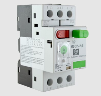 | MPCBs Dollex offers high-performance Motor Protection Circuit Breakers (MPCBs) engineered to protect motors from overloads, phase failures, and short... |
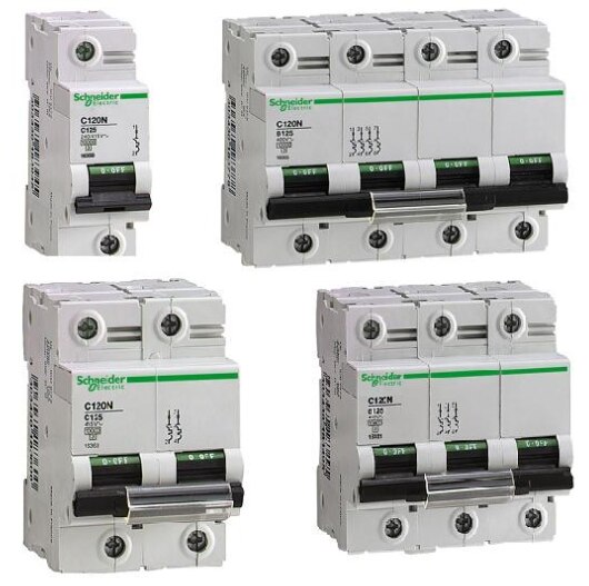 | MCBs At Dollex Control Panel Accessories, we offer a premium range of Miniature Circuit Breakers (MCBs) designed for superior protection and long-lasting... |
Frequently asked questions
What should you define before comparing switchgear devices?
Define the complete assembly: breakers, fuses, isolators, busbars, terminals, contactors, overload relays, metering, protection relays, enclosure, wiring and protective circuits.
Which electrical ratings must you verify at the installation point?
Verify system voltage, continuous load current and the prospective short-circuit current where the switchgear will be installed.
How do you match protective devices to a load?
Consider the load’s normal current, starting or inrush current, operating duty and likely fault condition before selecting breakers, fuses or overload protection.
Why does protection coordination matter?
Coordinated settings help the device nearest the fault operate first, while avoiding nuisance trips and unsafe operating or maintenance conditions.